Bowser Electric
Selecting the correct MCB breaking capacity protects people, wiring, and equipment during short-circuit events. A breaker may carry normal load safely, yet fail dangerously when fault current exceeds its interrupting rating. That is why many installers ask, “how to select the right breaking capacity for an mcb?” The answer begins with the prospective short-circuit current at the installation point. It also depends on system voltage, earthing arrangement, cable impedance, and upstream transformer capacity. Small errors matter.
This guide introduces ten practical tips for making that decision with greater confidence. It considers common ratings such as 4.5 kA, 6 kA, and 10 kA, while explaining why a familiar rating is not automatically suitable. During real panel assessments, engineers often inspect the utility supply, transformer distance, conductor length, and distribution-board location. A short cable run can allow much higher fault current. A remote circuit may experience less. These details deserve attention.
Reliable selection should follow the applicable product and installation requirements, including relevant IEC standards and the manufacturer’s technical data. Check whether the stated rating is Icn or Icu, and confirm the value under the correct voltage conditions. Coordination with upstream protective devices also matters. A higher breaking capacity may improve safety, but it does not replace correct overload protection or installation design. It is tempting to rely on a label alone. That shortcut needs reconsideration. The following tips connect calculation, field experience, documentation, and professional verification, helping readers avoid assumptions that can leave an MCB under-rated when protection is needed most.
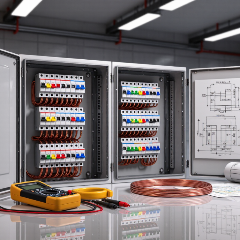
MCB breaking capacity is the highest prospective short-circuit current an MCB can interrupt safely. It is usually stated in kiloamps, such as 6 kA or 10 kA. This value is different from the rated current, which protects wiring against overload. A 20 A MCB may still need a 10 kA breaking capacity.
When selecting an MCB, an electrician should estimate the fault current at the installation point. The supply transformer, cable length, conductor size, and upstream impedance all affect this value. A short cable near a large transformer can produce a much higher fault current than a distant socket circuit.
The selected breaking capacity must equal or exceed that calculated fault level.
Check the marking carefully. It should match the technical documentation and the installation standard used for the project. A 6 kA device may be suitable in a small domestic board, but that assumption can fail near commercial equipment. Coordination with upstream protective devices also matters, because backup protection may change the permitted arrangement. Do not rely only on the MCB’s current rating. It is an easy mistake. During inspection, verify terminal tightness, conductor size, enclosure condition, and available fault-current data. If the calculation is uncertain, selecting a higher breaking capacity may offer a safer margin, but it does not replace proper circuit design. Even experienced installers can overlook future supply changes.
Selecting an MCB starts with the prospective short-circuit current, not the load current. This is the fault current expected at the device terminals. IEC 60909-0 provides calculation methods for low-voltage fault conditions. IEC 60898-1 lists standard breaking-capacity values, including 3, 4.5, 6, and 10 kA. A 6 kA MCB is not automatically suitable. A nearby transformer may produce a much higher fault level.
Measure or calculate the current at the actual installation point. Include transformer rating, impedance, conductor length, conductor cross-section, and supply configuration. For example, a 100 kVA transformer with 4% impedance can deliver about 3.6 kA at its secondary terminals, before cable impedance reduces the value. The result changes along the circuit. Never copy the value from another building without checking its supply data.
Tip: Request the utility’s maximum fault-current figure, then verify it through an IEC 60909 calculation. Compare the calculated value with the MCB’s rated short-circuit capacity. Leave engineering margin where supply upgrades are possible. A neat spreadsheet can still be wrong if the transformer impedance is outdated. Field verification matters. Also check the installation category, ambient temperature, and backup protection requirements. Breaking capacity addresses fault interruption; it does not replace correct overload coordination or periodic testing.
Selecting the right MCB breaking capacity starts with the actual system voltage and fault current. The device must withstand and interrupt the prospective short-circuit current at its installation point. IEC 60898-1 defines the relevant test and performance requirements for household and similar MCBs. A 6 kA rating is not automatically suitable for every 230/400 V circuit. Check the supply transformer impedance, cable length, conductor size, and measured fault level. Verify the MCB’s rated operational voltage and pole arrangement, especially in direct-current systems. AC assumptions can fail badly in DC circuits. Use installation records, not guesswork.
Earthing conditions also change the protection decision. In a TN system, a low earth-fault loop impedance can produce enough current for rapid MCB operation. In a TT system, higher impedance may prevent reliable overcurrent tripping, making residual-current protection essential under IEC 60364-4-41 principles. The MCB still needs adequate breaking capacity for line-to-line and line-to-earth faults. Measure loop impedance at the farthest outlet, then compare it with the disconnection requirements. Do not rely only on the label.
NFPA’s Electrical Fires report, covering 2015–2019, found electrical distribution and lighting equipment involved in 24% of home fires and 43% of direct property damage.
That evidence supports careful verification, although an MCB alone cannot remove every electrical risk. Field conditions are often less tidy than drawings suggest.
Selecting an MCB means matching its breaking capacity to the available fault current. Breaking capacity shows how much short-circuit current the device can safely interrupt. Common classes include 3 kA, 4.5 kA, 6 kA, and 10 kA. These values are not interchangeable. A 3 kA unit may suit a small, low-fault residential circuit, while a 6 kA device is often preferred for modern homes and light commercial systems. Always check the installation standard and local requirements.
Measure or calculate the prospective short-circuit current at the MCB location. Consider the transformer size, cable length, conductor impedance, and supply arrangement. A short cable from a large transformer can produce a higher fault level than expected. Commercial buildings may require 6 kA or 10 kA protection. Industrial panels can need even higher ratings, especially near substations or large motors. Check the MCB voltage rating, pole configuration, and approved backup coordination with upstream protection.
Do not choose only by price. I have seen neat schedules hide incorrect fault-current assumptions. The highest available rating is not automatically the best choice, either. It must coordinate with the distribution board and the cable system. Installation records should show the calculated fault current and selected rating. An on-site measurement can reveal differences from design drawings. That detail matters. Have a competent electrical professional verify the selection before energizing the circuit.
Top 10 Tips to Select the Right MCB Breaking Capacity?
Verify Compliance, Coordination, and Manufacturer Specifications
Selecting an MCB breaking capacity starts with the prospective short-circuit current at the installation point. A rating that looks adequate may fail near a transformer or distribution board. Measure or calculate the fault level using the supply impedance, cable length, and transformer data. Do not rely on a general household assumption. That shortcut can be costly.
Compliance must match the installation’s location and governing electrical standard. Check the required test rating, voltage, frequency, and pole configuration. Then review coordination with upstream and downstream protective devices. An MCB may interrupt the fault safely, yet still trip too slowly for the cable or connected equipment. Selectivity tables can help, but they are not universal. Verify the exact device combination.
Manufacturer specifications deserve careful attention. Confirm the rated breaking capacity under the correct test conditions, not only the large number printed on a sales sheet. Check temperature derating, enclosure effects, terminal limits, and installation orientation. In field inspections, I have seen technically correct selections fail because the enclosure changed heat dissipation. That detail is easy to miss. Also examine backup protection requirements and approved combinations. If data is incomplete, pause the selection and request written technical evidence. I once treated a simplified fault estimate as sufficient; it was not. Rechecking the calculation exposed a much higher fault current.
| No. | Selection Tip | What to Verify | Relevant Data or Requirement | Why It Matters | Recommended Evidence |
|---|---|---|---|---|---|
| 1 | Determine the prospective short-circuit current | Assess the highest prospective fault current at the MCB installation point, including utility, transformer, cable, and source impedance. | For a balanced three-phase fault, a simplified estimate is Ik ≈ ULL / (√3 × Zk). Use the applicable network study method for final verification. | The device must safely interrupt the maximum fault current available at its terminals. | Short-circuit study, utility data, transformer impedance, or verified measurement. |
| 2 | Match the rated breaking capacity | Compare the available fault current with the MCB’s declared breaking-capacity rating at the actual voltage and installation configuration. | Select an interrupting rating that is equal to or greater than the prospective short-circuit current. Common ratings may include 4.5 kA, 6 kA, 10 kA, or higher, but the required value depends on the system. | A lower interrupting rating can cause equipment failure, fire, or an unsafe arc during a fault. | Product marking, technical datasheet, and applicable test certificate. |
| 3 | Distinguish Icn, Icu, and Ics | Use the breaking-capacity term required by the applicable product standard and equipment category. | Icn is commonly used for MCBs covered by IEC 60898-1. Icu and Ics are commonly used for circuit breakers covered by IEC 60947-2. Do not treat the values as interchangeable without verification. | Different standards use different test procedures, ratings, and application assumptions. | Applicable standard declaration and manufacturer test data. |
| 4 | Confirm voltage, frequency, and pole configuration | Check the rated operational voltage, frequency, number of poles, neutral arrangement, and earthing system. | Verify compatibility with the system voltage, such as single-phase or three-phase service, and with the required pole switching arrangement. | Breaking performance and isolation behavior can depend on voltage, poles, and circuit configuration. | Circuit diagram, nameplate data, and product rating table. |
| 5 | Select the correct trip curve | Compare the circuit’s normal inrush current and fault-clearing requirements with the instantaneous trip characteristic. | Typical instantaneous magnetic ranges are approximately 3–5 × In for B, 5–10 × In for C, and 10–20 × In for D, subject to the applicable standard and manufacturer tolerance. | An unsuitable curve may cause nuisance tripping or fail to provide the intended protection. | Load-starting data, cable impedance, and published time-current curves. |
| 6 | Coordinate with upstream and downstream protection | Review selectivity, backup protection, and the operating sequence of adjacent protective devices. | Coordination must be verified using time-current curves, energy let-through values, or tested coordination tables for the actual device combination. | Proper coordination can limit unnecessary shutdowns and help isolate only the faulty circuit. | Discrimination study, coordination chart, or tested combination data. |
| 7 | Use cascading or backup protection only when verified | Check whether an upstream protective device is permitted to provide backup protection for the selected MCB. | A downstream device with a lower standalone rating may be acceptable only when the complete combination is tested, documented, and applied within its stated limits. | Unverified cascading can leave the downstream device exposed to fault energy beyond its capability. | Combination tables, test reports, and installation instructions. |
| 8 | Account for temperature and grouping | Apply correction factors for ambient temperature, enclosure conditions, ventilation, and adjacent energized devices. | Use the manufacturer’s derating tables. The marked current rating may not represent the usable continuous current under all installation conditions. | Thermal derating affects overload operation and can increase nuisance trips or reduce allowable loading. | Panel layout, ambient-temperature data, and correction-factor tables. |
| 9 | Check conductor protection and installation rules | Verify that the MCB rating and trip characteristics protect the conductor against overload and short-circuit effects. | The design should satisfy the applicable relationship between design current, protective-device rating, and cable ampacity, including installation-method correction factors. | A high breaking capacity alone does not guarantee correct overload or cable protection. | Cable calculation, installation standard, and voltage-drop verification. |
| 10 | Verify manufacturer specifications before approval | Confirm terminal limits, tightening torque, mounting position, conductor size, service conditions, accessories, and certification. | Use the exact model’s technical documentation; do not rely solely on the nominal current or a similar-looking device. | Small differences in construction and tested combinations can change breaking capacity, coordination, and installation suitability. | Current datasheet, declaration of conformity, installation manual, and inspection checklist. |
It shows the maximum short-circuit current the MCB can safely interrupt. Common ratings include 3 kA, 4.5 kA, 6 kA, and 10 kA.
No. It may suit a small residential circuit with a low fault current. Modern homes may require 6 kA protection.
Measure or calculate the prospective short-circuit current at the MCB location. Consider transformer size, cable length, conductor impedance, and supply arrangement.
A short cable has less impedance. Near a large transformer, it can allow a much higher fault current than expected.
Commercial buildings often require 6 kA or 10 kA protection. Industrial panels may need higher ratings near substations or large motors.
Not always. The MCB must coordinate with the distribution board, cables, and upstream protection. A larger number alone proves little.
Check voltage, frequency, pole configuration, temperature derating, enclosure effects, terminal limits, and installation orientation. Small details matter.
It is essential. Confirm approved combinations and selectivity data for the exact devices. General tables may not apply everywhere.
Pause the selection and request written technical evidence. A rough estimate may look convincing, but it can be wrong.
A competent electrical professional should verify the calculation, installation conditions, and compliance before energizing the circuit. Check twice.
Selecting the correct MCB breaking capacity is essential for reliable circuit protection and safe system operation. The breaking capacity indicates the maximum prospective short-circuit current the MCB can interrupt without failing. To understand how to select the right breaking capacity for an mcb, begin by estimating the prospective short-circuit current at the installation point, considering the transformer, cable length, conductor impedance, and available fault current. The selected value should be equal to or higher than the calculated fault level.
Next, confirm that the MCB rating suits the system voltage, phase arrangement, and earthing conditions. Different breaking capacity classes may be appropriate for residential, commercial, or industrial applications, but the choice should always reflect the installation’s actual fault risk. Finally, check applicable electrical standards, coordination with upstream and downstream protective devices, and the manufacturer’s technical specifications. Proper verification helps prevent nuisance tripping, equipment damage, and unsafe interruptions while ensuring the MCB performs effectively under short-circuit conditions.